
After driving my Model-A for a while with the stock 3-speed non-synchro transmission, it seemed like the car would be much more compatible with modern-day traffic if it had an overdrive gear. A company in Muncie Indiana, called Auto Restorations makes a kit for installing a Borg-Warner T5 transmission in a Model-A. The kit costs $895, and includes transmission adaptor, driveshaft, brake linkage changes, clutch disk, speedometer cable, etc. Presumably everything you need. After a call to get information (765 288-3291, they dont have a web site) I ordered a kit.
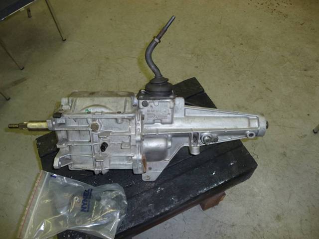
The only thing you need to know before ordering is how many splines there are on the input shaft, so that you can get the proper clutch disk. The donor transmission comes from a Chevy S10 2WD pickup. These T5 transmissions are unique in that they have the shifter placed further forward than a standard T5. Even though the shifter is further forward, it still is about six inches rear of the original Model-A shifter once the conversion is done. T5 transmissions are synchromesh in all gears and high gear is 0.72:1, a nice 38% reduction of RPMs while cruising. My transmission had the 14-spline input, but some of these T5s have a different spline count. I believe all have a standard 27-spline output. I found a transmission at the local Pull-A-Part for about $70 including tax and the core-charge. They arent very difficult to pull out, but I did donate a nice socket to inside the frame of the donor vehicle while I was taking off the cross brace. Heres what it looks like:
The kit arrived, well packaged, in two boxes. Many of the parts were primed in red oxide. I though that it would have been a nice touch if the supplier had powder-coated them, and I considered doing that myself, but decided instead to paint everything in black prior to installation. In retrospect, Im glad that I didnt powder-coat them, since several parts needed to be modified.
Instructions are included, but they are pretty sketchy and in unusual order. I suspect that no word processing was used so that modifying and updating the instructions had long ago ceased. They do include some good pictures and drawings though, that I found to be very helpful. I didnt have any idea if this was going to be a half-day or week-long job. As it turns out, the latter was the closest guess. If you want to see the instructions that come with the kit, here's a copy...
T5 Installation Instructions.pdfFirst thing I did was to modify the transmission. This involves cutting off a tab behind the shifter and drilling a hole below the shifter to accommodate two thick steel plates that bolt to the rear of the transmission. These plates are the new support for the rear control arms connecting to the axle. As was going to be typical in this job, the plate on one side had to be machined to fit the transmission, and the spacers from the kit werent quite the right size, so I ended up making new ones. Also, the hole in the T5 needs to be bored to a larger size to work with the kit.
The next step was to start disassembling the car. This involves unbolting the rear spring, brake rods, and shock absorbers from the car so that differential can be lowered and moved back to remove the torque tube. Heres one step in the instructions: Go to the back of the transmission and remove six bolts holding the torque tube. At the differential this torque tube should release so it can be taken down. If not, you may have to persuade it.
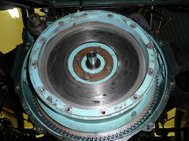
Those two sentences turned into hours and hours of work. As it turns out, removing the torque tube at the rear involves pulling the pinion bearings (complete with races) from the differential. After several hours of unsuccessful persuasion, I found a note tacked onto the end of the instructions about how to use a disk and some studs included with the kit to help. Finally, success! Here it is at work:
Once the torque tube is out, the transmission can be removed. Its not a bad time to also take out the brake linkage since it will all be modified anyway later on. When the transmission is out, the new clutch disk can be installed, using the existing pressure plate. The instructions tell you that you need to get an alignment tool, but they actually included a decent plastic tool for this purpose. The kit also doesnt mention, but includes a new pilot bushing that slips into the existing flywheel bushing, and extends it out and to the correct diameter for the T5. Forgetting that would be something you would remember for a long time since it would require pulling out everything again. You can see it in this picture.
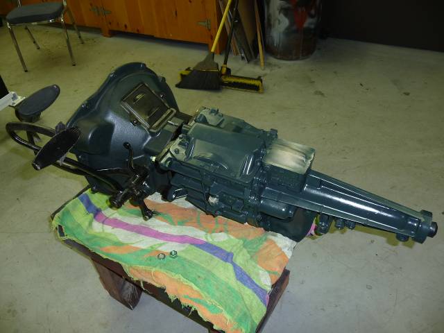
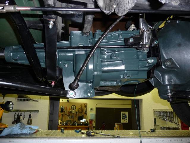
The kit includes an adaptor that mates the Model-A bell-housing with the transmission. I was concerned that it didnt accurately locate itself on the transmission it was only located by the bolts, which have some slop. I pondered welding and machining to make it fit tightly around the transmission input shaft, but then realized that it was the same situation on the bell housing side, and there was nothing to reference it to there either. Ive read elsewhere about making sure that the transmission is aligned to the motor within a couple of thousandths of an inch, and consequently was nervous. I called Auto Restorations, and was connected with Mr. Lewis, who must be the owner. He said not to worry about it, just bolt it together and it will work. He was right. Maybe whats right for a car that works up to 2,500 RPM is different than whats right for a car that works up to 6,000 RPM. It was necessary to redrill the mounting holes on the transmission to accept the bolts included with the kit, and a couple of the bolts were the wrong length, but it all went together in the end, and when painted up, looked like this:
It was necessary to drill a hole for a cotter key that holds one end of the clutch return spring, you can see it above, just behind the inspection cover on the bell housing. A sleeve, included with the kit, slides over the input shaft tube of the transmission to make it the correct diameter for the Model-A throw-out bearing.
You cant see it on this picture, but the other side of the transmission contains a bracket for holding the emergency brake. Much to my surprise, it moved several inches to the right not exactly friendly for the passenger. The bracket didnt fit as sent, and they forgot to drill the holes. Mr. Lewis gave me the location of where to drill the holes, and then I redid the poor weld and machined it where it interfered with the gearbox.
Prior to installing the transmission, it is necessary to, gasp , cut an opening in the front of the cross member of the frame. It looks like this when you are done:
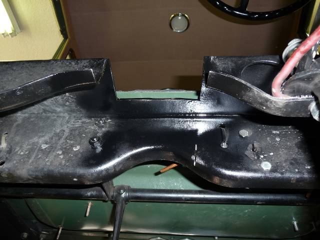
I didnt like the idea of cutting the frame, but saved the piece that I cut out, and figured that it could be welded back in again if desired. The new transmission mount that bolts under the cross member restores some of the strength lost by cutting.
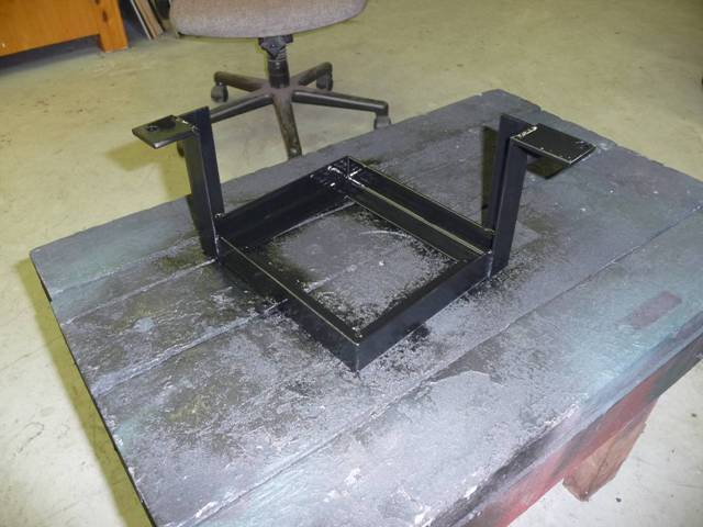
The new transmission mount needed to be reworked by heating with a torch and bent slightly to give the correct fit for my car. It installs with two new holes that you drill in the cross member.
Once the transmission is bolted back into the car, I turned my attention to the differential. The kit contains a nicely machined input shaft and housing for the front of the differential. This converts it from a torque-tube to an open driveshaft. The housing is meant to also house the speedometer sender. You take the gear from the original torque tube, and machine it so that it slips over the new shaft, then pin it in place with a tension pin. When locating the gear, dont believe the drawing you get with the instructions, the dimension it gives you is off by an inch. The original speedometer drive bolts onto the outside of the new housing in front of the differential, and a long speedometer cable is included with the kit that reaches all the way back there.
I wondered why you couldnt just connect the speedometer to the transmission, so called Mr. Lewis. He said that there isnt any reason why you cant, its just that some of the later transmissions dont have provisions for a speedometer. I like the idea of using the transmission output, and the speedometer was calibrated closely when I used the 0.833:1 adaptor that was on the S10 truck.
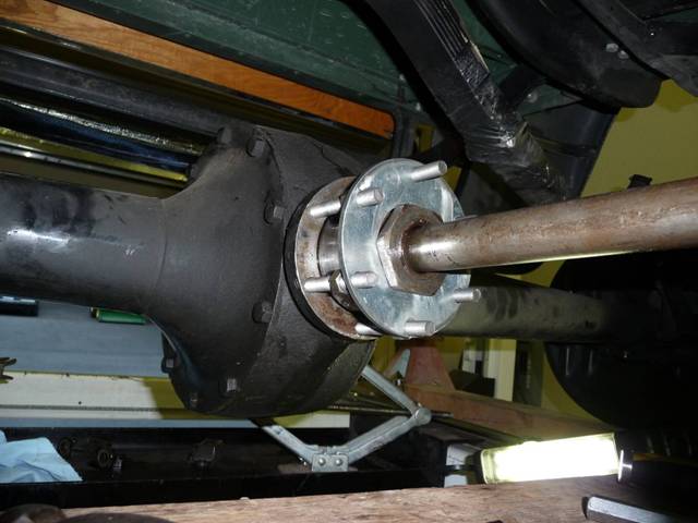
The driveshaft (included with the kit) fits well, although I think it could be about an inch longer so that it would engage more of the splines in the transmission output shaft. Also, I was disappointed that at the rear, you install the U-joint to the differential input shaft with a small key (no splines), and then install a nut inside the U-joint, which is very difficult to tighten. I ended up grinding down a big wrench, but still couldnt get it very tight in that space. It will be really tough to remove too, especially after a cotter pin is installed. A flanged arrangement would have been much better.
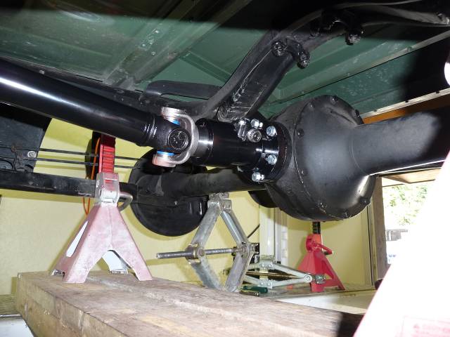
Heres what the rear looks like now:
At this point, the drive train is pretty much complete, time to turn to the braking system.
However, in my case, I stopped to weld up a new battery box. When the car was converted to a 12V system, the new battery was smaller, and I decided that it would be better to have a correctly sized battery box for it. This also allowed installation of a disconnect switch under the floorboard.
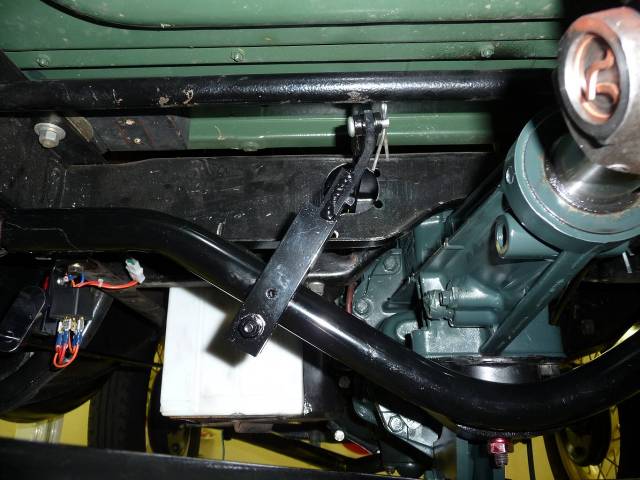
The first step for the brakes is to relocate the main pivot arm (crossbar) to the rear. It moves to behind the cross brace in the chassis. This requires drilling four new holes in the chassis, but they are small ones. The kit comes with a new crossbar and all new operating rods. The instructions show that you connect the rod from the pedal to the cross-shaft at a pretty severe downward angle. This actually reverses the direction of the crossbar, and I didnt like the angle of the lever and rods it just didnt seem right. So I changed it to run the operating rod in the same general orientation as was stock, Henry Ford did a lot of good things, and I think this general setup was good too. This required one more hole in the frame cross member, and welding up an extension to the lever arm, but the geometry looks good now. The rods are also in generally the same location too, so they fit through the guides similar to original. Heres what the setup looks like from the rear of the crossbar:
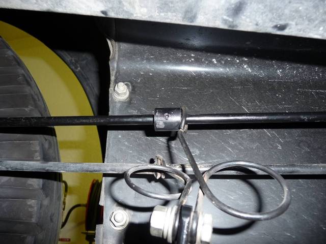
Were getting pretty close at this point. The new brake rods all fit fine, except the one from the pedal to the cross shaft, which needed to be shortened after my geometry change. However, there are no previsions on the new rods for the anti-rattle springs. I can live with a little rattling, but these springs are also there to pull the brakes back away from the drums and lift the pedal. So I machined some short extensions to where the rear anti-rattle springs mount, and then machined a stop that slides over each rod with a set-screw to capture the spring and put tension on the rod. Just below the stop that I installed, you can see the remaining factory equivalent on the lower emergency brake rod:
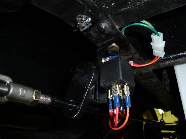
Only one brake detail left - the brake light switch. Even though my kit was ordered for a 30/31 car, it must have assumed that you would use a switch from an earlier car since mine wasnt even close to fitting on the bracket that they provided. So I made a new little assembly consisting of a micro-switch operating a relay. It works fine, but it doesnt look like it came from the early 30s:
Now that we are getting dangerously close to filling up that T5 with a couple quarts of Dextron ATF, there are only a few details left.
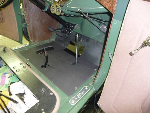
Its necessary to make a new floorboard and metal cover in the middle. Since both the shift lever and emergency brake have moved significantly, the original floorboard isnt usable. Plus its nice to save it in case someone wants to reverse all this some day (and thats not going to be me!). Heres the new floorboard made out of plywood.
I used my torch to heat up the T5 shift lever to bend it straighter. That was a little unnerving since you cant disassemble it because its clamped together, and there are plastic parts just a few inches from where you are heating and bending. Fortunately the vise took enough of the heat headed that way to make it work.
Now, look at that little beauty sticking up in front of the seat!
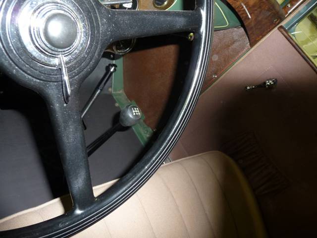
Ive since changed back to a more traditional looking knob by drilling and tapping an early Ford knob to a 10mm x 1.5 thread. The T5 is metric in its entirety.
The only other comment that I have about the installation is that changing the control arm position to accommodate the T5 puts quite an angle on the U-joints. You can see that here:
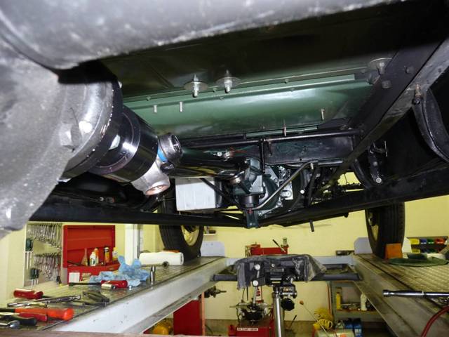
Heres a shot of the tranny installed. You can see in this picture (behind the disconnected speedometer cable) where the pivot for the rear control arms is located. Its about six inches lower than the stock location.
So, how does it work? Really well. I thought that the big advantage would be having overdrive, but as a practical matter, most of the improvement is from being able to row through the first four gears so easily. Now its practical to rev it up more before shifting, easily downshift at higher speeds, and having the new 3rd gear that fills that giant hole that existed between 2nd and 3rd on the original gearbox is invaluable. Its much easier to stay with the flow of traffic now. 5th is nice once youre rolling along on the level at 50 or more, but dont expect to go up steep hills in 5th. Actually, if you could have something with a slightly lower overdrive ratio it would be better.
This was a lot of work. Had I known that going into it, and without knowing the actual benefits of the conversion, I dont know if I would have done it. However, now that Ive been using it and see how much nicer it is to drive, I think it was time and money well-spent. If you decide to do it though, and use the same kit, just dont expect to easily bolt it together in a couple of afternoons as I initially thought. And plan on needing some like a gas welder, grinder and drill press (or milling machine). The kit is invaluable to doing the job - things like the motor plate and machined parts for converting from torque tube to open rear end would be extremely hard to fabricate on your own. And while the kit takes some tweaking to install, it is still a good value for what you receive. After you open the boxes of parts and examine them, its obvious that Mr. Lewis isnt getting rich from selling these kits.
Note: I've received several emails after writing this. One warned me about the safety of the conversion - the writer's thought was that without the torque-tube, the rear control arms are required to handle more stress, and the old original ones may not be up to the task. He suggested changing the control arms during the conversion, using stronger ones such as those offered by Auto Restorations. I've also had a couple of contacts expressing frustration with the design and/or quality of the kit. If you have done this conversion, and would like to have your email address listed on my site as a contact for other readers, let me know and I'll put it here.
Note: Since writing this, Auto Restorations has closed their doors, and the kit described in the write-up is no longer available. However, another source for T5 conversion parts is:
Their offerings are shown here, but may have changed, so contact the shop directly for more current information.
![]()