

In the early 80's, I decided to make a wireless mailbox alarm system for my folks as a Christmas present. Living in the country, their mailbox was hundreds of feet from the house, they didn't know when the mail or paper was going to arrive, and hence, over time lots of unfruitful trips were made to find out if it was there.
The goal was to have individual indicators in the house that would go off when either the mail or paper arrived, and a reset button to turn them off. While the original design was workable, this is a project that has gone on for over twenty five years, and I'm my third revision of the design at this point.
For the first design, I used the guts out of a pair of walkie-talkies in the receiver and sender. To differentiate between the two signals (mailbox and paperbox), I used DTMF (dual-tone, multi-frequency) encoder/decoder ICs. These were the ICs used in telephones that would generate and receive the tones used with touch-tone phones. So, for example, when the paper came, a switch closed, and actuated the walkie-talkie with the same tone as when pressing the "2" button on the phone. When the mail switch closed, it would send the tone equivalent to pressing the "3" button on the phone. Meanwhile, the receiver in the house would encode these signals and turn on the appropriate LED.
For actuation switches, I used two different approaches. On the mailbox, I mounted a mercury switch on the door, so that when it was opened, the contacts would close and that would power up the transmitter and decoder. On the paperbox, there was a swinging door suspended from the top. I mounted a magnetic burgler alarm sensor to the box, and a magnet in the door. An advantage of this approach is that wires don't need to move when the door swings open and shut.
Of course, there is the potential that one of these switches might remain closed, and run down the transmitter batteries. So I put a one-shot in the transmitter so that power would shut off after about half a second, even if the switch was still closed.
This design worked for a number of years, but eventually corrosion got the best of the transmitter circuit. Tough to deal with electronics that live outdoors. A weaknesses in the design was that if one of the switches remained closed, the other switch wasn't recognized. The one-shot kept everything shut down until both switches were open.
When the first unit expired from corrosion, rather than ripping apart walkie-talkies, I made a second design with transmitter/receiver ICs from Abacom in Canada. For this version, I used similar power-down circuitry (one-shot), but in place of the DTMF chips, I used Holtec encoder/decoder ICs in conjunction with the Abacom transmitter/receiver modules.
This design is still in use many years later at my mom's home, but has a couple weaknesses carried over from the original design. It turns out that the door on the paper-box had a tendency to swing back and forth from the wind, or when cars went by, and battery life became very short. So I had to disconnect the switch to the paperbox. I had also changed to a single 9V battery on this revision, and the transmitter battery life isn't as long as I calculated, even with only the mailbox.
I decided that I would like to have a unit at my home too since I live in the sticks of Washington, with the mailbox a long way away from the house, and in addition, it is located over a small hill and through heavy woods. I discovered that the ICs I used from Abacom weren't available anymore, so it was necessary to redesign it again.
This time, I continued to use the Holtec encoder/decoder ICs, but switched over to transmitter/receiver modules made by Linx Technologies. While it's easiest for most of us to use through-hole parts on home projects, these modules are SMT, but are reasonably easy to solder by hand. I also decided that it would be nice if the receiver chirped when the mail came, so I added that feature. For the mailbox switch, I used the light-switch from a refrigerator. When the door opens, the switch pops out and closes the contacts to the transmitter. Finally, I also figured out a way to eliminate the one-shot so that there aren't issues with one of the switches staying closed.
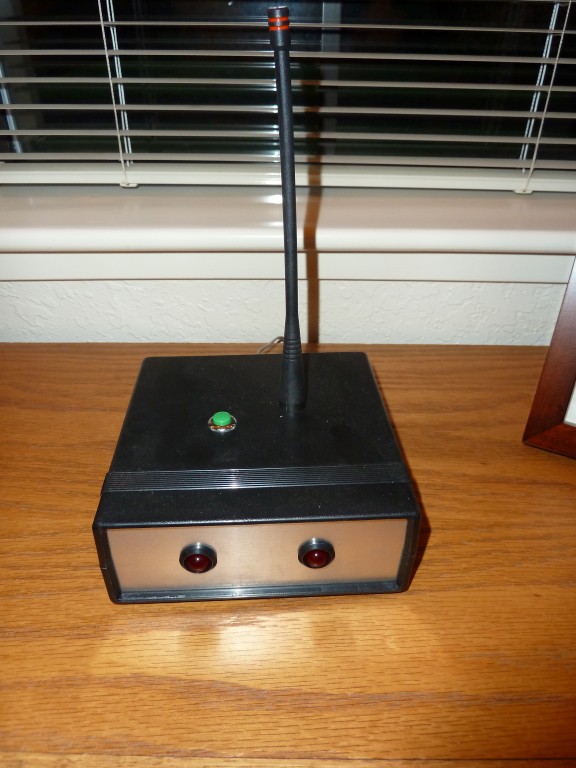
This is what the receiver looked like before labeling the LEDs on the front. The green button on the top resets the LEDs. The circuit inside accepts up to four unique transmitter codes, but I only installed two LEDs on this unit.
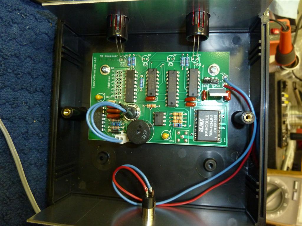
Here are the insides of the receiver. The circuit board is attached to the lid of the enclosure. The blue wires are connected to the reset switch. On the back is a jack that goes off to a 9V wall-pack. I was able to source all the parts other than the PCB for this project from DigiKey. I use ExpressPCB for my circuit boards. After growing up in the era before CAD, it still seems amazing to me that I can enter a schematic and do a PCB design using the free tools available from ExpressPCB, then get three PCBs back a few days later for about $75. If I don't need the entire PCB area for the project I'm working on, I use the spare area for little bread-boards and the like, then cut them off using an 1/8" burr cutter. You can see the Linx module in the lower right - note that even though it's SMT, the leads are gold plated and extend far enough out and apart to be manually soldered without difficulty
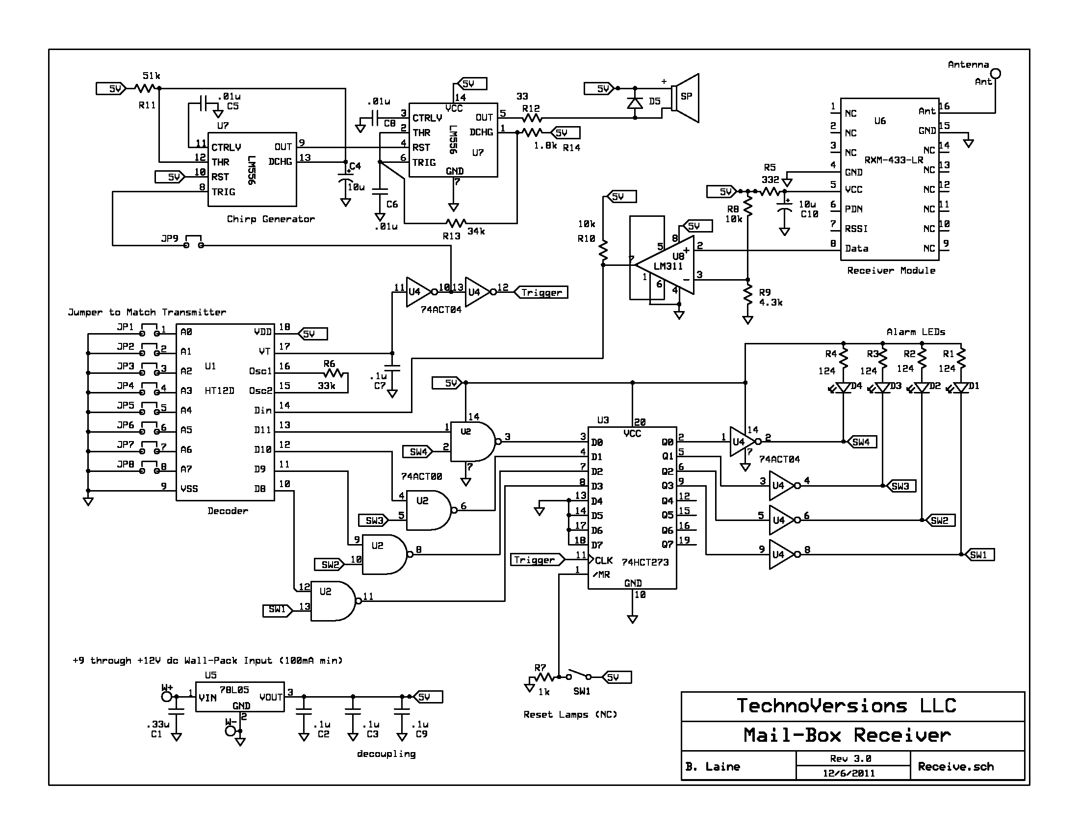
The receiver works well, but the beeper isn't as loud as I would like. If I ever do another revision, I'll look into that. For the chirper, I used one half of U7 to generate a chirp length, and the other half for the chirp frequency. It drives a 2 KHz electromagnetic buzzer. With my bad hearing, I needed a lower frequency like this to be able to hear it.
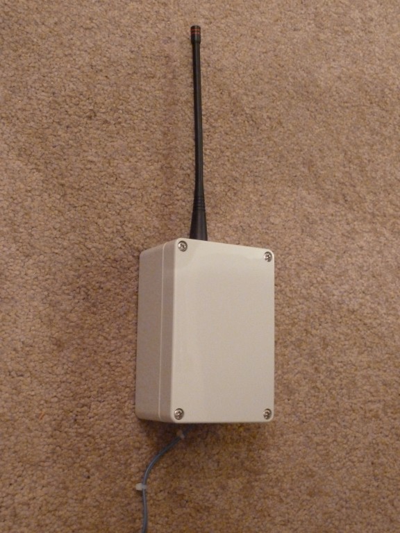
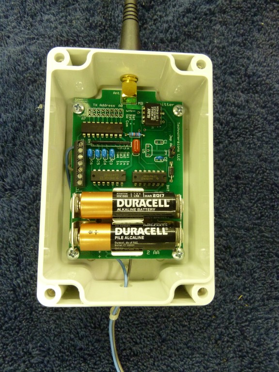
This is what the transmitter looks like. It's installed in a weatherproof enclosure. I mounted it on a tree a little ways from the mailbox, and ran wires from the bottom of the transmitter to the mailbox switch.
Here is the interior of the transmitter. I designed it to use two AA cells, which are installed. I also designed a voltage regulator into it, thinking that if I needed more battery life I could connect a bigger battery pack via a couple of the terminal strip screw connections. Battery life is fine with the two AAs though.
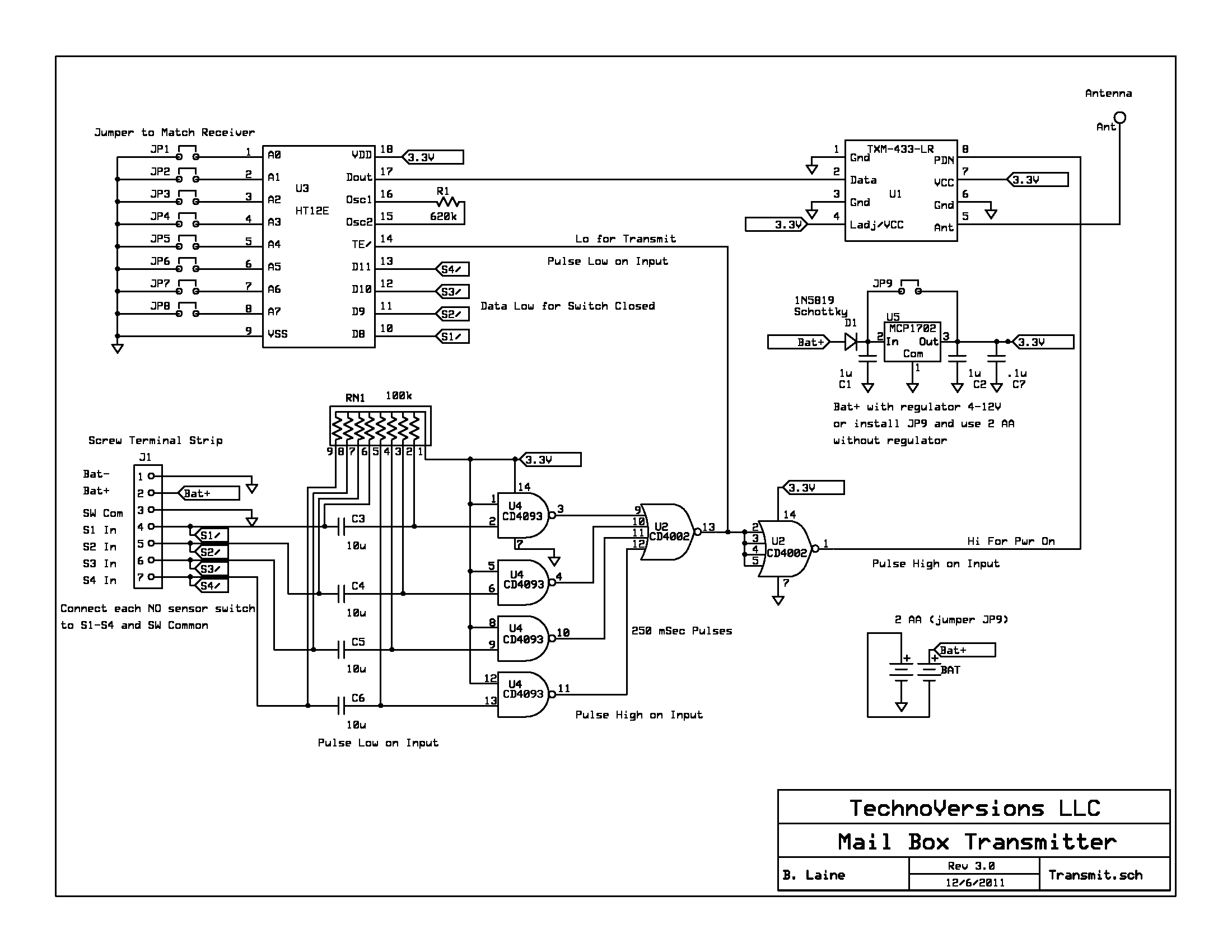
Very simple schematic. The key to battery life is the Linx transmitter that can be connected to VCC all the time, but has a power-down pin (PDN) so power can be reduced to almost nothing when not transmitting. The resistors in RN1, in conjunction with C3-C6, form an RC time delay that makes the transmit signal stop even if the switch stays closed. This method fixes the bug of the first design that the other channels didn't work if the switch stayed closed on one. If you only need to transmit one channel, the design could be simplified somewhat.
The Linx transmitter/receiver ICs (TXM-433-LR/RXM-433-LR) work at 433 MHz. The claimed range is up to 3,000 ft. I had trouble getting range anywhere near that - but then I had a difficult environment (woods, hills), and not much RF expertise (at best). I ended up messing around with ground planes to get the range I needed. I spent a lot of time on the transmitter end, but it turned out that the receiver side was a little more problematic - I didn't expect that. In any case, I'd recommend good ground-planes on your PCBs. Linx also offers a development kit which I didn't initially know about. It's a way to test range and experiment with the ICs and a known-good layout prior to doing your own layout. I would recommend getting this if you are working with ranges beyond a couple hundred feet.
It's fun to work on projects like this, and a challenge if you know little to nothing about RF, like me. One of the bigger challenges is to trouble-shoot and debug the system if it isn't working. Is it the transmitter or the receiver that is the problem? I finally concluded that having an extra transmitter and receiver, or at least an extra transmitter, is a good way to go - that way a problem can be identified to be on either the receiver or transmitter side, which is a good start.
With the multiple channels available on the receiver, I can see other things that you could accomplish with additional transmitters. Maybe an alarm to let you know if an intruder is on the premises? This could be triggered by a driveway sensor, or even from a light circuit that senses motion. How about a shock-detector mounted to a mole or gopher trap? That way you would know when it's time to check it. The possibilities are endless given the variety of sensors available today.
A possible enhancement would be a real-time clock in the circuit that would log the date/time when the alarms occur. That way you would know when the event was occurring, and you would also know if someone was in your mailbox other than you or your postman.
Something that this project has highlighted is how cheap some of the remote devices are these days. You can buy complete remote items for ten bucks in some cases - and they work fine. That cost won't get you past but a few components on your own design, let alone the cost of the PCB, enclosure and your time. But these typically have a short range, and in any case, it's a lot of fun and very satisfying to do your own design.