
I decided that it would be nice to have an engine run-in stand. place to bolt a motor, then fire it up and run it for break-in, tuning, and to find and fix any problems, such as leaks, before doing the final motor installation.
You can buy engine run-in stands, but they arent cheap, and then involve truck shipping since they are so large. Plus, its fun to build things.
Heres what I built:
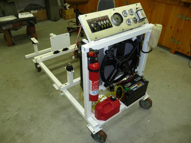
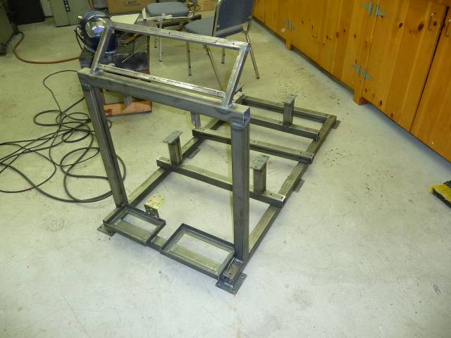
I made it out of 2 square tubing with heavy 0.12 thick walls. The overall size of the base is 30 by 60. A friend donated some extra casters he had. The stand needs to be high enough so that the legs of your engine hoist will roll below. In this case, 7 ½ was just enough for my hoist.
At one end, I welded on two uprights. This is for mounting the radiator and control panel.
From Pull-A-Part, I got a Camaro radiator along with its cooling fan. A Nissan at the same yard donated a radiator overflow tank. I used the rubber pads from the Camaro top and bottom to mount it. The fan in the car was used in a pulling configuration (mounted behind the radiator). I tried it in both directions by changing wire polarity, and it worked, but was drawing very heavy current. Im not sure if I caused that by running it backwards, or whether it was just defective, but another trip to Pull-A-Part secured another fan that works fine without drawing too much current. Ive just let it run its normal direction though, I dont want to risk making another trip.
Below the radiator, I mounted a battery (with disconnect knob), a fuel tank, an electric fuel pump with regulator and pressure gauge, and a fuel filter. Also mounted on the uprights is a fire extinguisher I hope its never necessary, but nice to have just in case.
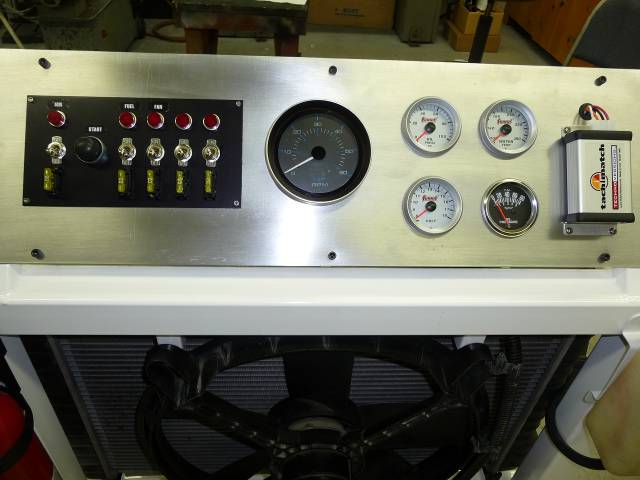
For the control panel, I used some ¾ square tubing and aluminum sheet. I mounted a tachometer (from a boat), a TachMatch so it can be switched to accommodate engines with different number of cylinders, a voltmeter, oil pressure gauge, and a water temperature gauge. I also put in an extra hole for future, which I temporarily filled with another oil pressure gauge.
When I was buying the small gauges at Summit, I also ordered a Moroso switch panel. This has a starter button, and a number of switches with on-indicator lamps, and a fuse per switch. I wired it up so that I have an on/off switch for the ignition which also powers the other gauges, the starter switch, a fuel pump switch, and a fan switch. That leaves a couple switches for future expansion.
I used several relays in the wiring. Theres a horn relay used to switch the fan, and another to switch the ignition current. I also got a starter relay from a Ford at Pull-A-Part so that the cable connecting from the battery to the starter is only active when the starter button is pushed. This is necessary for cars without starter relays (like Fords), but is also compatible with cars that use a solenoid on the starter. I like this approach since theres less likelihood that you will accidently connect the high-current cable to something bad when it is hot. On the other side of the stand, I installed a ground cable.
Ive made three motor adaptors so far. One is for a flathead Ford V8, and another is for a small-block Ford V8 (289, 302, 351), and the last for a Datsun A-series engine/transmission. These are simply cradles with rubber mounts. I used common inexpensive transmission mounts that connects the cradle to the motor. The cradle clamps to the main 2x2 frame so that it can easily be adjusted back and forth.
At the transmission end, I made a plate that bolts where the transmission typically would mount. I drilled patterns in the plate for three common Chevy and Ford patterns. The plate connects to the frame via a couple more transmission mounts, same as in the front.
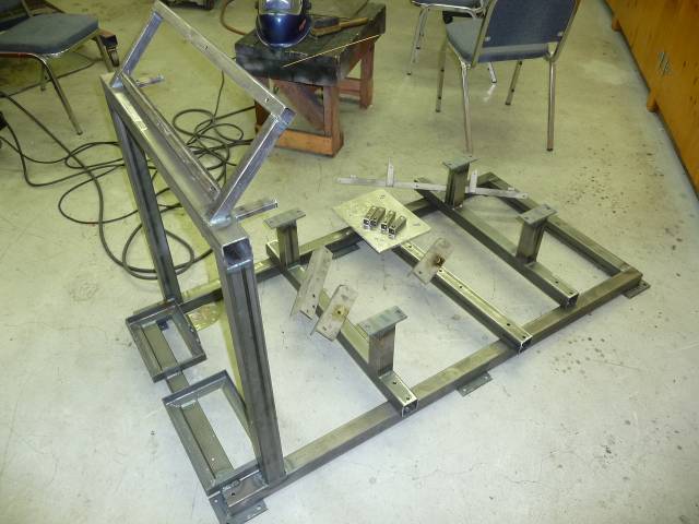
Once I had it all welded up, I took it down to the local powder-coating company and had them powder-coat everything. I figure since it was going to be exposed to gas, oil, hot water and abrasion, it needed to be tough. They charged $100 for the job. Here are all the parts ready to be coated:
The first motor I ran on it was a Ford flathead V8. It was expensive to hook up the radiator since these motors have two water pumps and two hoses per pump. However, 16 connections and hose clamps later it ran without leaking. The radiator cooled it well,and the vibration when running was minimal.
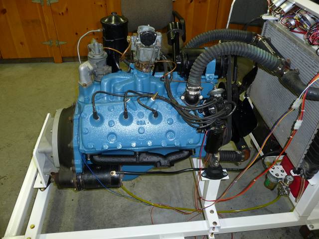
With this motor, the gauges worked a little strange. As I revved the motor, they would start fluctuating wildly at times. Im not sure why this is. It may be interference from the ignition wiring, in which case I might need to make a grounded shield for the back of the instruments. I bought inexpensive generic Summit electronic gauges, so that may be the problem, Ill wait until I do the next motor to see if its a chronic issue or unique to this motor.
I've run my second motor on it, a Ford 302 stroker motor. In order to make it work, I had to add an MSD ignition and coil to the stand, which I did below the radiator on the "drivers" side. That was because I was using a magnetically triggered distributor that couldn't directly run a coil.
Here's what it looks like with this motor:
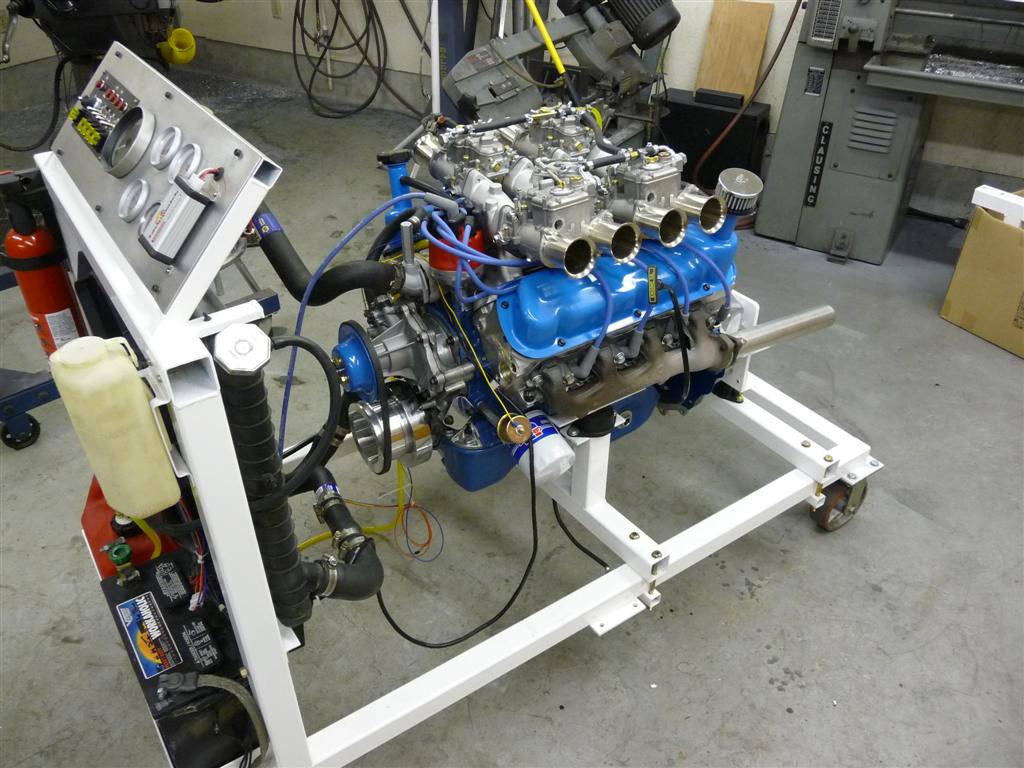
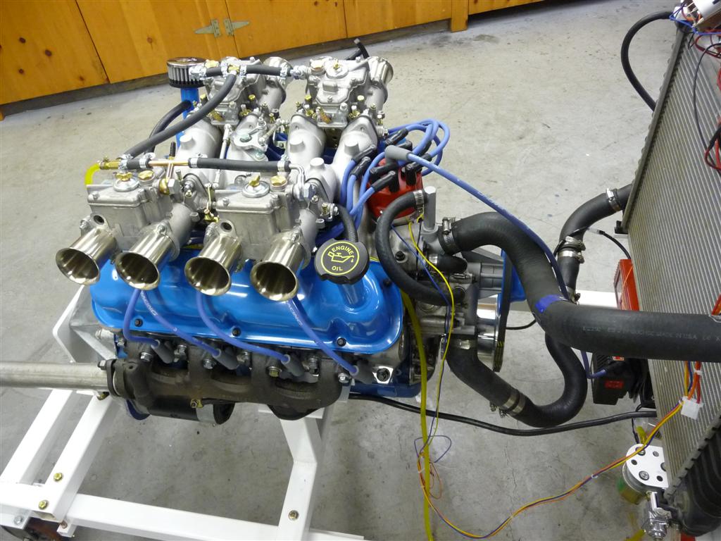
I found that the gauges work fine with this project. I had installed both mechanical and electrical oil pressure gauges on the instrument panel since I had an extra hole for expansion - this motor had an oil pressure "issue" and it was nice to have both gauges to be able to confirm proper operation of the gauge and sender. At the local Pull-A-Part I found a single top hose that worked, and was able to cut up and join four for the bottom hose. Lots of clamps, but inexplicably it doesn't leak.
I had put some extra caster pads in the middle of the stand, just in case I needed them. As it turns out, I didn't need them, and the middle pads are about where the front motor mount wants to be with this motor. I suppose I should have left the pads off. This is a high power motor though, and when you hit it, there is some flex in the stand.
One other minor change I would make. I wired it so that the gauges turned on with the ignition. Next time, I would have a separate switch for the gauges. This would allow you to leave the ignition off, but still turn over the motor and watch the oil pressure gauge as you prime the oil system prior to fire-up.
The stand saved a lot of work on this project. I had made an assembly error on this motor. So in addition to getting the motor tuned up and tested, it allowed me to find the problem and easily fix it prior to installing the motor in the car (and having to pull it again).
PS - this is a LOUD motor with little 12" long straight pipes. What little hearing I used to have must be even less now. Would be nice to have a muffler set-up. Better yet, also a way to run the exhaust outside the shop. Not that the entire stand can't be rolled outside.
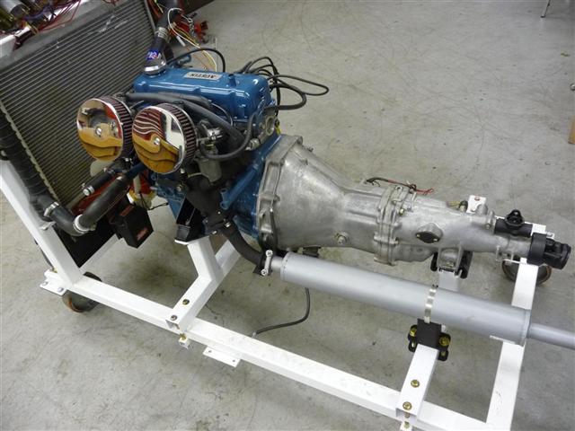
I made an adaptor for Datsun A-series engines, the push-rod motors used until the early eighties in the smaller Datsuns. In this case, the transmission doesn't have a removable bell-housing, so I decided to mount the whole transmission on the stand. Then, I got fancy and installed a muffler. A Massey Ferguson tractor muffler worked great.
I had modified this engine for dual British SU carburetors, so it was nice to be able to tinker with it out of the car to get the initial tuning and linkage worked out. Also gave me a chance to ensure that I had the electronic distributor and alternator wiring sorted out.
I've had several requests for more measurements, so here are the overall dimensions that I used. There isn't complete detail since some of the parts I just fabricated on the fly without drawings. I still haven't built a small-block Chevy mount (amazingly enough), so if you do, please send me the dimensions and the motor mounts that you used, and I'll add that information to the site.
Laine Engine Stand Drawings