
After driving the Z8 some, I noticed a couple of things about the 289 motor that I originally installed. One, it was smoking sometimes, and two, while it was fast, it wasnt the "blow your socks off" kind of fast. If youre like me, you dont build a car like this to be simply faster than average, you want it to be a little outrageous.
I saw an ad on CraigsList for a package of parts that included a 5.0 high performance block with a stroker kit to get it up to 331 cubic inches. The kit had fresh machining of the block for these parts, and included a stud girdle, Mahle pistons, etc. If you arent familiar with small block Ford strokers, a standard 5.0 (302) has a stroke of 3.0, the 331 has a stroke of 3.25, and the 347 has a stroke of 3.40. All have similar bores since the thin-wall 302 block isnt conducive to large overbores. My bundle of new parts came complete with balancer, rods, crank, bearings, rings and aluminum flywheel. Fortunately for me, the seller's wife was pregnant, otherwise he wouldnt have been desperately selling his neat goodies. Meanwhile, on another CraigsList listing, I found a set of new aluminum Ford Motorsport GT-40 Turbo Swirl heads. Nothing like aluminum heads to reduce the Z8s weight even more, add better breathing, and allow you to run a higher compression ratio on pump gas.
A friend who is an avid Ford performance nut got me in touch with a friend of his who is even more knowledgeable and more of a performance nut (hard to imagine). Rick, for the love of performance and to be a very nice guy, volunteered to lend a capable hand to the engine build.
We started mapping out a motor with a four-barrel and aggressive Edelbrock intake manifold. After Rick did some work on this combination, I ran across a manifold on eBay that provided for the use of four Weber DCOE side-draft carburetors on a small-block Ford. Unfortunately, someone else beat me to the punch, but after pestering the seller for a few months, he came across another manifold for me. Fortunately Rick didn't tell me to take a hike for a major change of direction after he'd been working on the original approach.
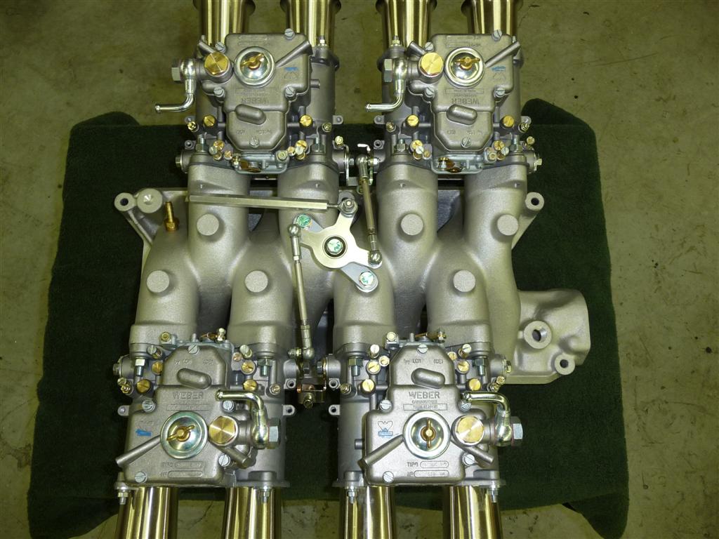
Here's the manifold much later, after adding carbs and linkage - I thought I would show you a picture now, though, to keep your interest. Otherwise you might be going back to your game of Solitaire.

When I first did the Datsun, I wanted to use a manifold with four Weber 48 IDAs downdraft carbs, thinking that this was the perfect mix of continental GT flavor and an American motor. I tried to make a set work, but they just wouldnt fit into the Z8 since they ran into the hood latch and hood brace. But Im a sucker for the look and performance of Weber carbs, so was excited to find something with a brace of Weber that does fit. Of course, it was all theoretical at that point that it would fit but a few measurements looked very promising.
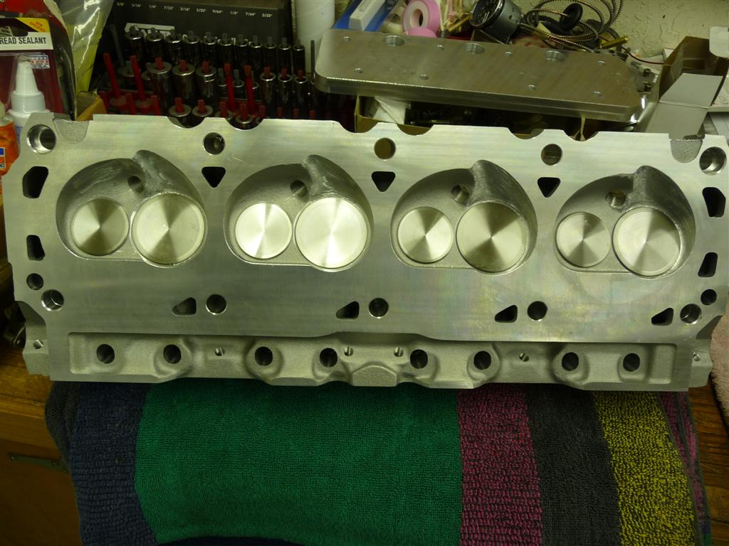
Rick has a flow-bench, and was able to flow the heads and manifolds reporting that they flowed quite well. He spent some time cleaning up the ports and port-matching the intake and heads. This manifold is a single runner manifold, meaning that there is no plenum just one carburetor barrel and a dedicated runner per cylinder. Good for low end torque. We figured that it would flow good to about 5,500 RPM before the power started to fade. Bear in mind that even though there are eight 45mm (1 ¾) barrels, since they arent shared between cylinders, this isnt as much carburetion as it seems at first glance. While he was working on the heads, Rick got the compression ratio up to 9.9:1 about the max you can run with pump gas perfect! Here's a head shown from the piston's perspective...
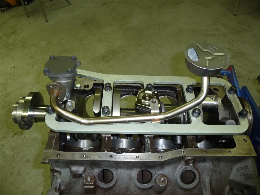
I started to assemble the short-block while Rick was working on the top end. Since my Datsun uses a Fox body rear sump pan, it was problematic to get the oil pickup over the top of the stud girdle, and under the pan. The only way I could make it work was to modify a pickup to orient it slightly differently. I also had to replace the Ford Motorsport pan with one from a Mustang in my local Pull-A-Part junkyard very similar, but it just had a little more room in there. I did learn from the Ford Motorsport pan kit that there are new one-piece rubber pan gaskets available now a very nice way to seal up the bottom of the motor. With a little modification, I also was able to use some of the dip stick parts from the pan kit.
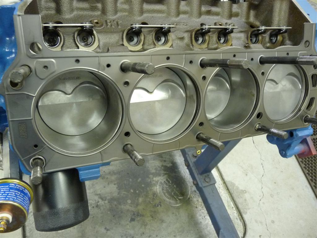
Here's the short block as it starts to come together...
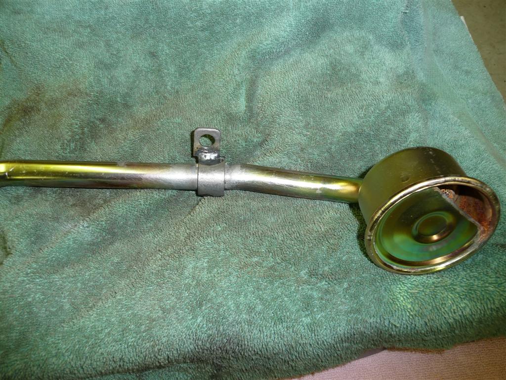
Here's how a standard pickup wants to fit with the stud girdle. Not even close...
But with a little tweaking and welding, one can be made to work...
Another problem was that the dip-stick orientation on a rear-sump pan made the dip-stick want to bump straight into the stud girdle. To fix this, I made an angled tube and installed it through the stud girdle, attaching it with a setscrew (with lots of LocTite). It guides the dip stick through the stud girdle and angles it down into the pan.
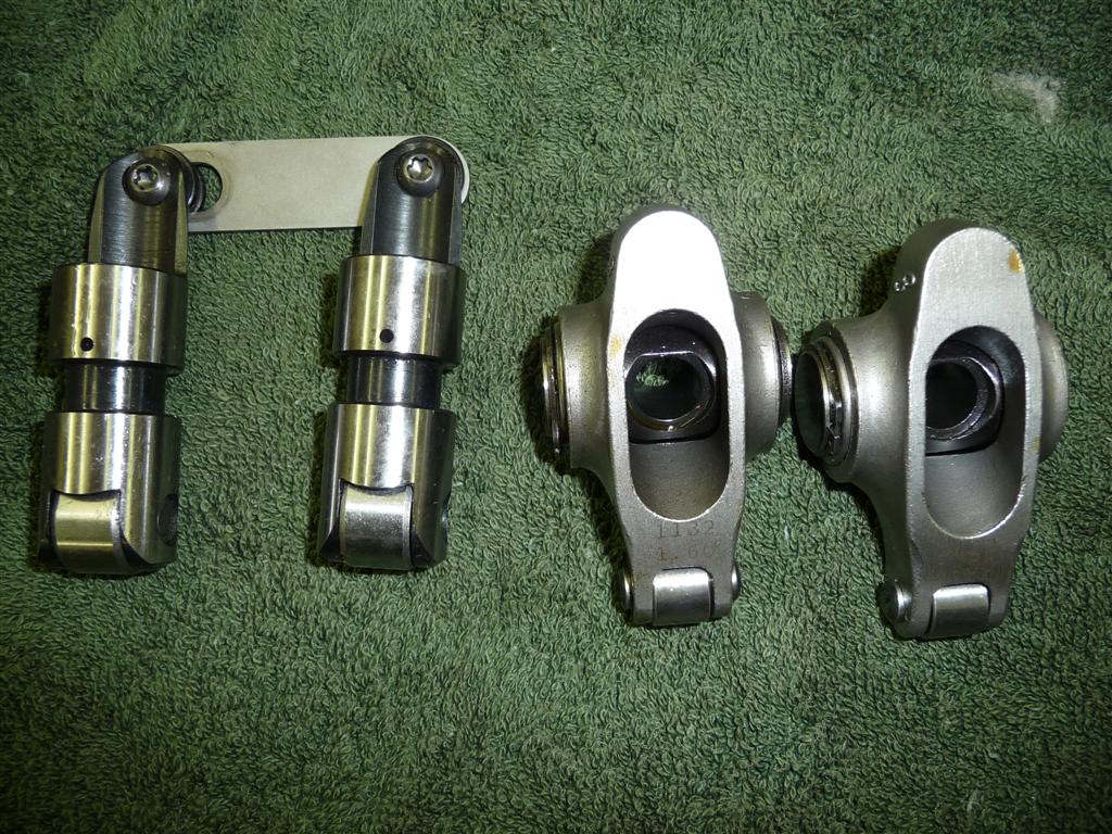
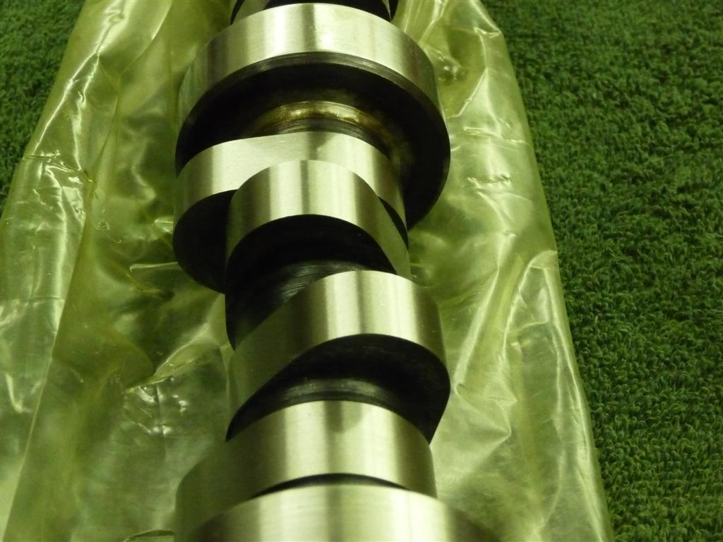
Rick recommended a fairly aggressive roller cam, so as per his recommendation I installed a Comp Cams cam that provided .6 of lift at the valves with duration of around 280 degrees. I used a 351 firing order as with previous builds. Meanwhile Rick configured the head with beehive valve springs and valves that could handle this sort of lift. He also installed rocker studs to accommodate the Comp Cams roller tipped rockers that we wanted to use since I already had them.
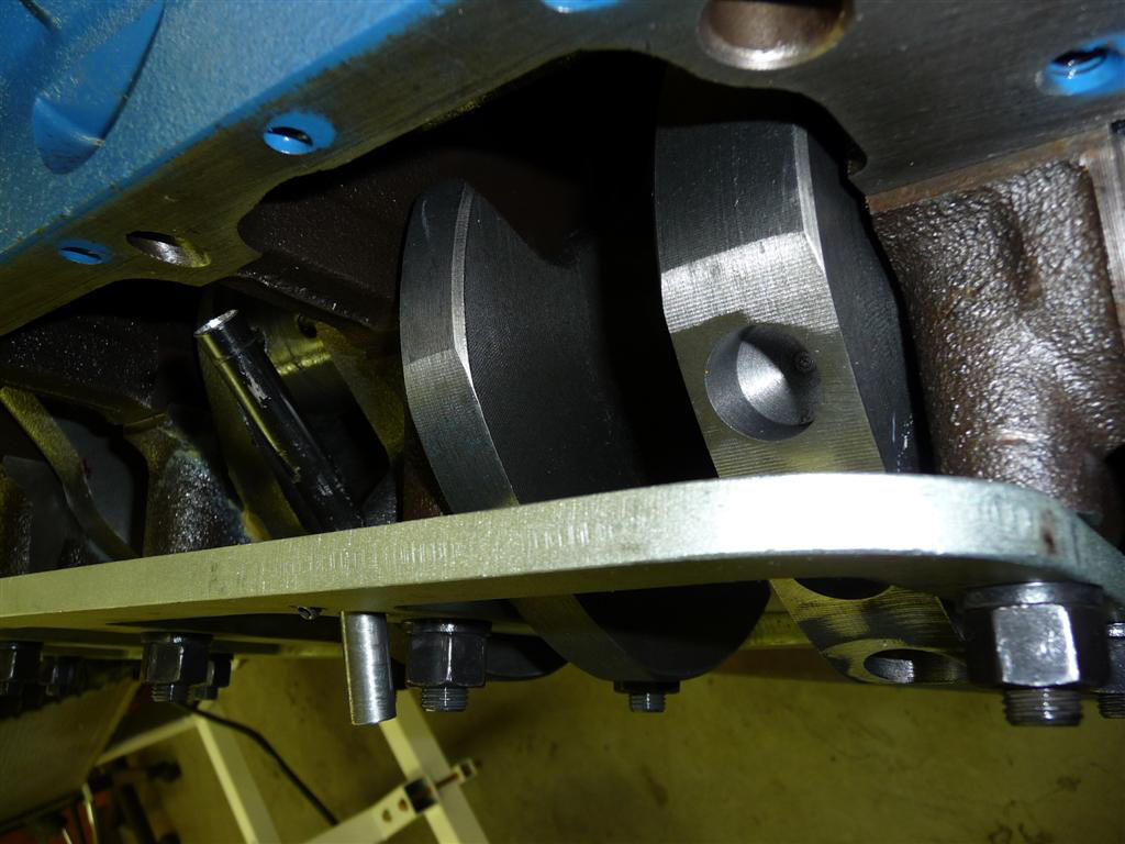
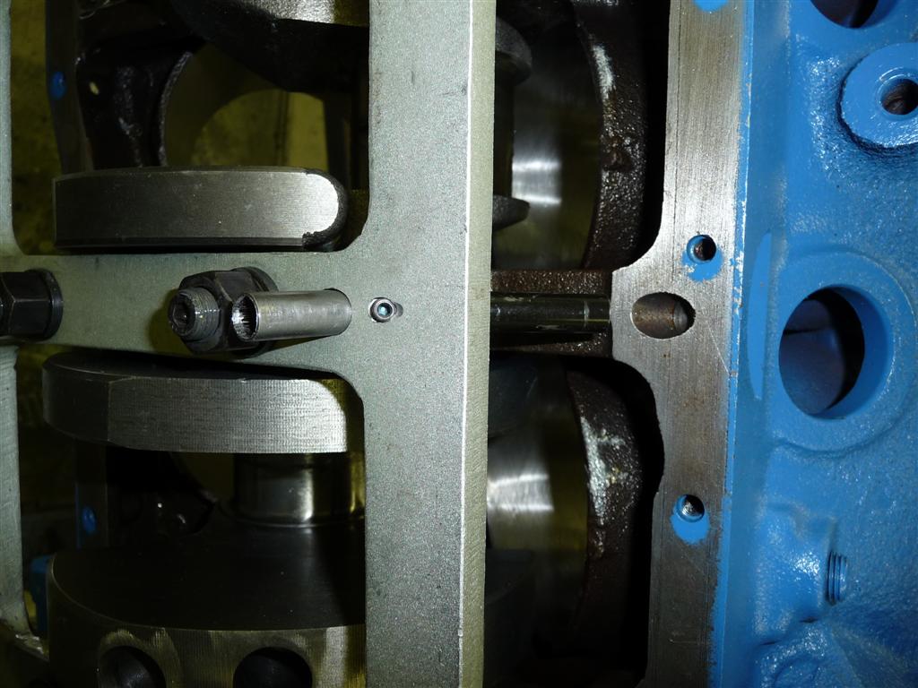
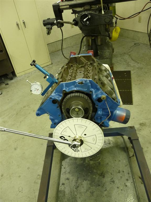
I installed an adjustable Cloyes timing sprocket so I could degree the cam. It was pretty close just using the factory setting, but was optimized by a degree or two. See that hole at the rear of the valley, on the ridge the intake manifold rests against? Remember that as you read ahead.
It was an exciting day when Rick was ready with the heads and intake. We came up with what looked to be the best pushrod length and I made some guide plates for the pushrods. Things are coming along. I discovered that there wasnt enough clearance between the Ford Cobra aluminum valve covers and the carburetors. Even if they fit on the outside, there would be some work necessary inside to modify the baffles to miss the valve train.
Dang, not quite enough room with these valve covers which I originally planned to use. This was even without valve cover gaskets.
After a day at Pull-A-Part taking off possible stamped-steel valve cover alternatives, I came up with some that not only cleared the valve train (with a little shortening of the rocker studs), but they also could be removed with the carburetors in place whew. After a trial fit, I used my trusty Eastwood powder-coating outfit to apply old-Ford blue to the valve covers, pan and front pulley.
These fit, both on the outside AND inside, hard to find a single set that would accommodate both. From looking at them, one would never guess what was inside.
After rooting through all my old Weber parts, and ordering a few new ones, I came up with the parts necessary to synchronize and actuate the carbs. I was happy to be able to drive both banks from the center, so the linkage goes directly to each carb, rather than through one of the throttle shafts on the way to the next carburetor. It took drilling and tapping a couple holes on the top of the manifold, but I couldnt see a way around that. I also drilled and tapped a hole in the rear for connection to the Zs power brakes. I designed and fabricated the bellcrank with the geometry to give full throttle with 1 1/2" inches of throttle linkage movement, which is what the Z provides with the earlier bellcrank I made at the firewall side. This bellcrank uses a ball bearing from a skateboard wheel.
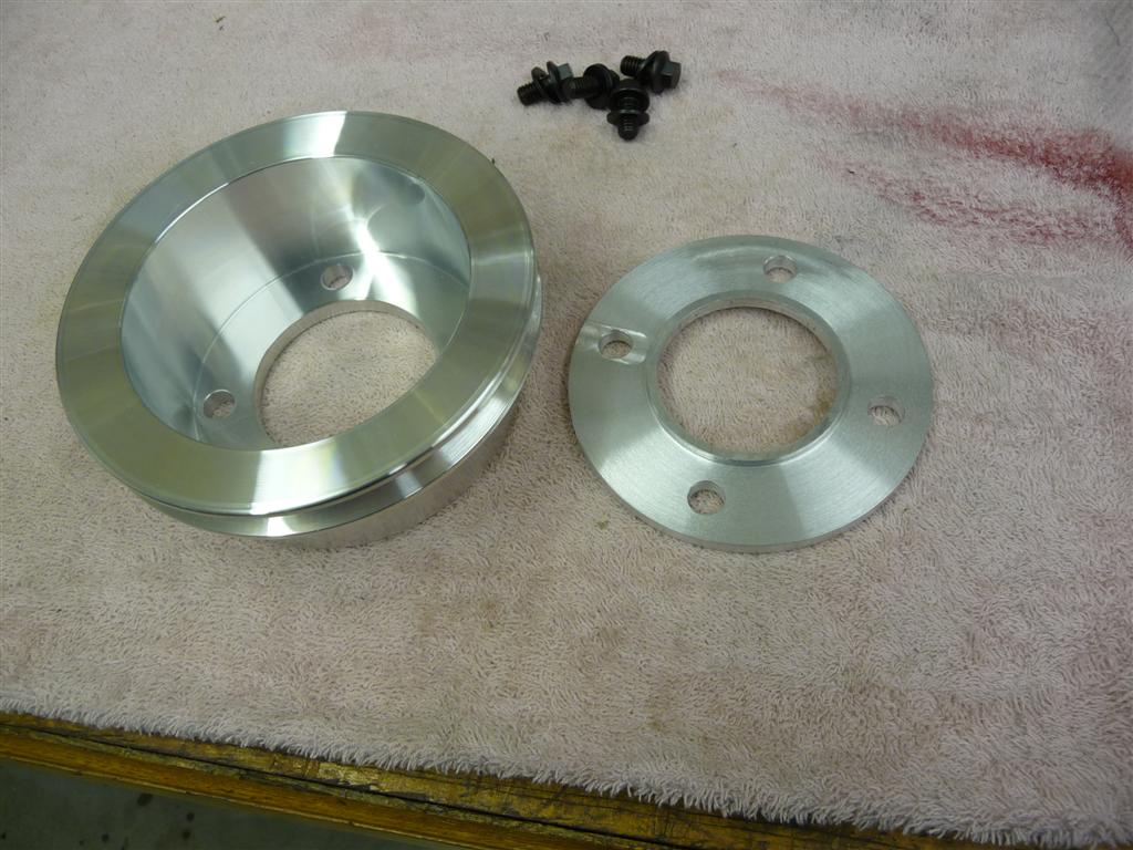
There were a couple of details to attend to next. The kit came with a CAT brand balancer. It seems to have an odd spacing for the crankshaft pulley. I could order pulleys with 3" or 3 1/2" offset, but this balancer seemed to want something in between. So I ended up getting the 3" one and machining a 1/4" think spacer.
The big day of firing up the motor was coming close. I decided to run it on my engine stand to see if there were any problems prior to installing it into the Z. If you're curious about the engine stand, there's a blurb about it elsewhere on my site. I installed an MSD 6 ignition box on the engine stand so that I could trigger it with the MSD magnetic trigger in the distributor. I found some vintage Mustang cast-iron headers for the run-in stand, with little 12 header pipes. What little hearing that I used to have has been reduced to even less now.
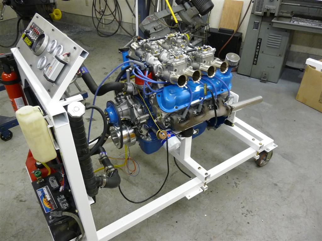
Look at all these hose clamps trying to make a few random used hoses from Pull-A-Part work. Can you believe that it doesn't leak? Ironically, it did leak a little at first, but that was from a hole in one of the hoses, not a connection.
The motor fired right up, but the oil pressure seemed low. It was only about 15-25 PSI. I double checked by hooking up a mechanical oil pressure gauge on my engine stand and unfortunately it was the same. So I tore the bottom end of the motor apart and discovered that some of the bearing shells were bad and there were aluminum flakes in the oil in the pan it wasnt getting enough oil. I installed new bearings and a new oil pump Im grasping at straws. Still low oil pressure. What I discovered in the end is that I had forgotten to install an oil gallery plug that is supposed to be in the rear of the lifter-valley. I should have known, but overlooked that. With the plug installed, the oil pressure was looking great, and the motor sort of idled (well at 1,800 RPM). With my experimentation solving the oil-pressure problem, I must have gone through a couple cases of engine oil by this time, but it gets drained yet again the engine seems solid at this point.
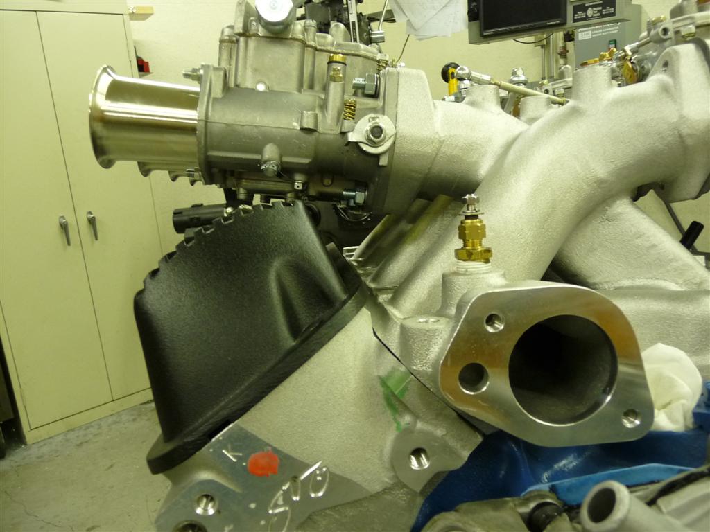
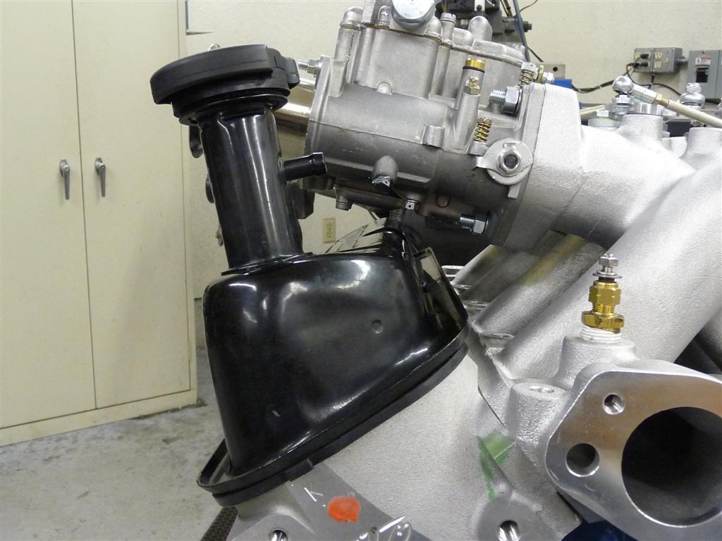
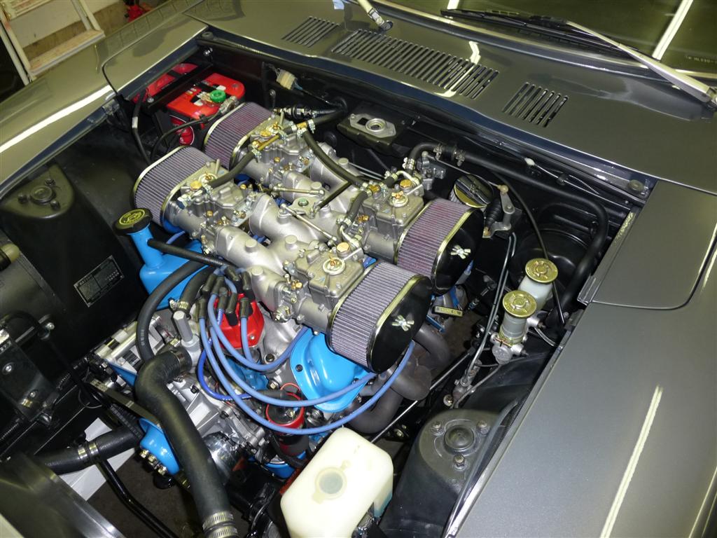
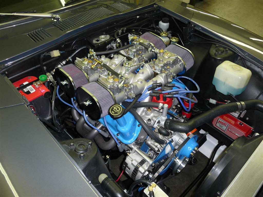
Into the Z8 it goes! I pulled out the old motor and squeezed the new engine into place. Indeed, the front end didnt settle quite as much from the weight loss of the aluminum heads. Here's what it looks like installed - hood closes and everything! At Rick's urging, I installed some air filters to protect the motor, but it was tough to give up the look of those individual velocity stacks. I suspect a little ways down the road (literally) I would have regretted it if I had not taken this advice. And I wouldn't consider the motor ugly, even with the filters.
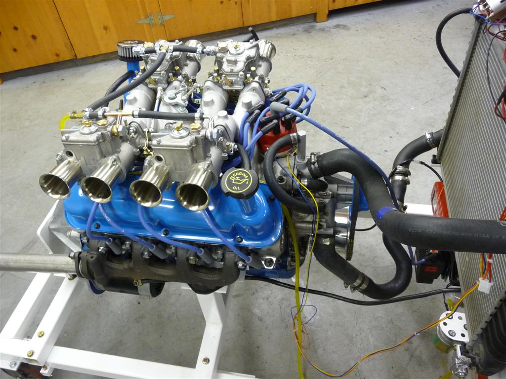
Here's what it looked like prior to the filters...
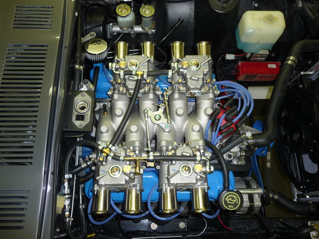
Here are the shots with the filters...
I installed the Datsun water temperature sender into the new Weber manifold and it leaked. It's a metric thread in a similar, but not exact, SAE thread as in the manifold. Worked OK in the previous manifold, but not this one. I started to figure out how to make a circuit to convert between a Ford sensor and a Datsun gauge, but found a book at CarQuest that showed the electrical characteristics of various sensors that they sold. I found a commonly available Ford sensor that was electrically very close to the Datsun sensor, and it seems to work fine - both mechanically and electrically.
Im still working out the details of the new motor, but I can tell you that this is one fast mama. I would guess that it must have at least 100 horsepower more than the old one. In fact, I was compelled to install a rev limiter in the car, and put tires in the rear that are about an inch wider than the earlier ones - they just barely squeeze in there. Now its the sort of car that really needs a track to explore it's limits - the street doesn't let you use many of its capabilities. Yet it still seems happy when sentenced to street use.
I owe a big thanks to Rick for his help in making this happen. As you can tell, I have great respect for Rick's knowledge. I've always considered myself to have above average car knowledge (don't we all?), but he's tiers beyond me. If you have a good question for him, he may share with you as well.
You can contact him via email Rick.
next section...